In the prior week our group was instructed that the gusset plates were able to become stronger with the increased number of connections. We then constructed a new bridge that partially followed our old design, but used far less amount of materials. The bridge proved to be to week and failed by twisting. The design was altered to strengthen the connections between the two sides of the bridge. This design wasn't able to hold as much weight and failed due to weak gusset plates.
In the next week we are going to move the support that protects against twisting to the top of the bridge instead of the bottom. We will also test the bridge to see what its max load is.
Major accomplishments for this week are having a bridge that follows our initial design, but with less materials than what we first tried. The bridge failures are also a promising factor as it shows that the bridge can vertically hold the weight; it just has a tendency to slide and twist on itself.
The issues that have arisen are that the bridge it structural weak when horizontal forces are put on it. The problem with fixing this issue is that the solutions cause for a weaker bridge in the vertical forces. The best solution will allow for no twisting while at the same time not sacrificing vertical strength of the structure.
What I have learned from the bridge design process is that everything aspect of design for a real bridge must be considered so catastrophes don't occur and no one is harmed. I learned that all truss designs are built out of triangles as these don't shift as squares and more sided shapes would. The forces on all the member can be broken down to see exactly what forces act on each member. The forces include tension and compression forces. I also learned that the weakest points on a bridge are the connections.
By Robert Weldon
Tuesday, May 29, 2012

Wednesday, May 23, 2012
Week 8
In the previous Lab we were given the chance to start
playing around with online Bridge Design and work on the A3 assignment. In the next lab we would making analysis and
calculations for the angles and triangles been used with Knex. We hope that the information provided by this
analysis will help us improve our design.
We hope to be able to maximize the strength of the bridge and minimize
its cost.
Both the hand and online Bridge Design calculations are
not sufficient analysis for building a real bridge. It is important to mention that there was
several significant limitations found with online Bridge Design. These limitations are expressed in
A3-Almendariz. As stated before, there
are much more forces and derivable that need to be considered for building a
real bridge design. Unfortunately these
calculations are only made for the side part of bridge and the calculations for
a third dimension is ignored. Also in
order to build successful bridge we need to consider much more outside factors
than the downward force resistance. We
need to consider what materials we would use, in order get a good ratio between
price and strength. Also we need to
consider the weather, type of ground, wind forces, etc. from the location where
the bridge is going to be built. There
needs to be a further study, calculations and testing to be made before been
able to come with a successful real bridge design.
A3-Almendariz
1.


2.


2.
Member
|
Force (N)
|
TAC
|
22.23
|
TAB
|
-31.44
|
TBC
|
31.44
|
TBD
|
-44.46
|
TDC
|
31.42
|
TDE
|
-31.44
|
TCE
|
22.23
|
Total Weight
|
44.45
|

3.

4. Using Online Bridge designer is an easier and
faster way to calculate the forces for a bridge design than calculating them
manually as before. Although the program
was really versatile for calculations, there were some important restrictions
found. Online Bridge designer had
restrictions involving the weight added, the scaling of length of trusts and
their angles, and position of nodes.
There was a small window for choosing the load been added, it is limited
to multiples of five. We would not be
able to know exactly the length of each trust that we are using and the angle
between them. These restrictions made it
difficult to know were was the right position for placing the nodes. In order to be able to correspond the results
from part 1 to bridge design we would need the right scaling for each component
and be able know and plug exact numbers for each components. It is important to note that although online
bridge design had it’s restrictions, the calculations given were reasonable
close to the calculations done by hand before.
5. 
While
trying to replicate our bridge design in online Bridge design program a big
restriction was found. Online Bridge
Designed required relating the numbers of nodes to the number of members. Our original bridge design had to be altered
in order to get it working with the program.
We were forced to take some members out and a node out. It is for this reason that these calculations
are not accurate.
6. The data provided by the results from the
testing of Knex Joints are really useful for the final design. The results from the testing showed that that
the more joint socked we used, it would create a stronger structure. We are able to know and give an estimate of
how much force each connector will be able to resist before it collapses. We would consider this data for improving our
next bridge design by trying to maximize it’s force resistance.
Week 8
In the prior week's lab, we learned what the Method of Joints is. Through the Method of Joints we began to construct the tension and compression forces that appear on a given bridge with constraints as to the height, length, and load on the bridge. This analysis helps to show what angles create better triangles that can hold more weight.
In the coming week our team will begin to analysis the triangles and angles used in our Knex bridge, same with the member lengths. We hope to find that we can cut costs in certain areas, and increase the overall integrity of the Knex bridge.
The major accomplishment of the week for the team was successfully able to learn and understand the Method of Joints and apply it to the constraint given 2-dimensional bridges and a 2-dimensional version of our team's Knex bridge.
Issues that may arise in the up coming weeks include unable to find the right members or members combination that increase the strength of our bridge. It may be that our bridge is already built to its full potential and nothing else can be done. It may also be hard to decipher our analysis of our Knex bridge using the method of joints.
The Method of Joints is not a sufficient form of analysis because it does not account for multiple loads on the bridge in areas other than the middle of the structure. It also does not account for horizontal forces such as wind and rain, which can add to the forces acting on the bridge. It would be a sufficient form of analysis if outside factors and change in the loads could be accounted for. To further analysis the bridge, tension and compression strengths of each member will need to be known to know what their breaking point is. What may help assist in this analysis is a more advanced program than WPBD, but one that measures the same information.
By Robert Weldon
In the coming week our team will begin to analysis the triangles and angles used in our Knex bridge, same with the member lengths. We hope to find that we can cut costs in certain areas, and increase the overall integrity of the Knex bridge.
The major accomplishment of the week for the team was successfully able to learn and understand the Method of Joints and apply it to the constraint given 2-dimensional bridges and a 2-dimensional version of our team's Knex bridge.
Issues that may arise in the up coming weeks include unable to find the right members or members combination that increase the strength of our bridge. It may be that our bridge is already built to its full potential and nothing else can be done. It may also be hard to decipher our analysis of our Knex bridge using the method of joints.
The Method of Joints is not a sufficient form of analysis because it does not account for multiple loads on the bridge in areas other than the middle of the structure. It also does not account for horizontal forces such as wind and rain, which can add to the forces acting on the bridge. It would be a sufficient form of analysis if outside factors and change in the loads could be accounted for. To further analysis the bridge, tension and compression strengths of each member will need to be known to know what their breaking point is. What may help assist in this analysis is a more advanced program than WPBD, but one that measures the same information.
By Robert Weldon
A3-Weldon
Method of Joints


The necessary steps for converting the hand analysis that was done to a format that Bridge Designer can use to give you the same results is a method of scaling. Bridge Designer gives you a grid to work on, you can set any number of inches to each square that fits the user. I set each square equal to 2 inches. Doing this made it possible for me to find the correct ratio of distance for all the nodes.
 One problem that we found using Bridge Designer was that it required the user to relate the number of nodes to the number of members used in the bridge design. Our bridge had more members than nodes so we were unable to test our actual design, but a similiar version was used.
This information about the method of joints greatly helps with the final design of our Knex Bridge. We will be able to see what the angles of the connectors produce in terms of tension and compression of the certain member that is in that location. We can then compare this information to the failure point of each size of Knex to see which piece will be best suited where, while still maintaining the design of the bridge and increasing its integrity.
By Robert Weldon

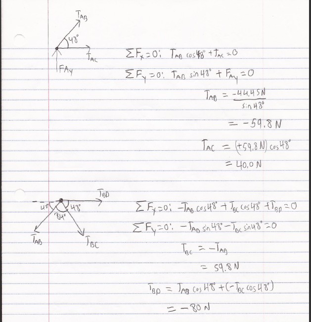

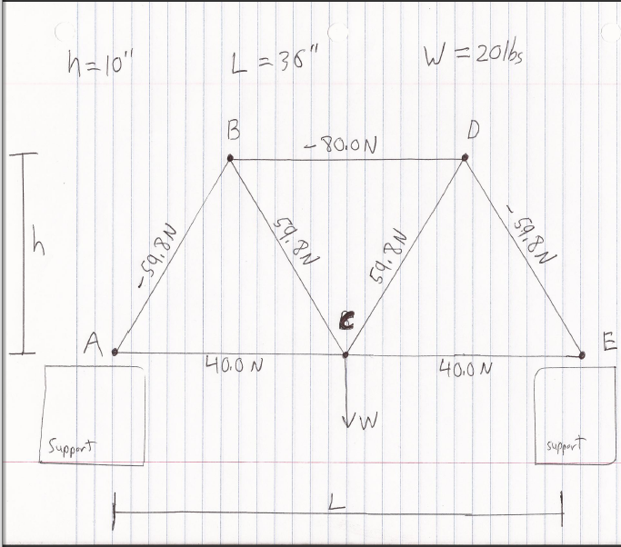
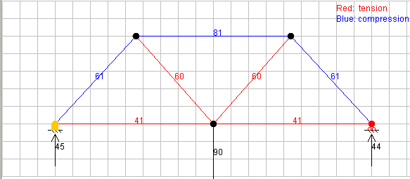
The necessary steps for converting the hand analysis that was done to a format that Bridge Designer can use to give you the same results is a method of scaling. Bridge Designer gives you a grid to work on, you can set any number of inches to each square that fits the user. I set each square equal to 2 inches. Doing this made it possible for me to find the correct ratio of distance for all the nodes.

This information about the method of joints greatly helps with the final design of our Knex Bridge. We will be able to see what the angles of the connectors produce in terms of tension and compression of the certain member that is in that location. We can then compare this information to the failure point of each size of Knex to see which piece will be best suited where, while still maintaining the design of the bridge and increasing its integrity.
By Robert Weldon
Tuesday, May 22, 2012
Week 8
During las week's lab we were introduced with a way of analyzing the forces on each part of a truss. This method is called the joint method analysis, this method basically analyzes the force on each junction. Using basic trigonometry the forces of tension and compression can be calculated. We spent the whole lab period doing calculations and figuring out how these forces will help us produce the best design possible for the final project. This week our focus will be to collaborate, and use the joint method analysis to improve on our current design and see how the design changes with the added length.
This method of analysis will be useful but not in all the situation we may encounter. Unfortunately this method of analysis only considers the front part of the truss, ignoring its third dimension. This method is also a very simplistic way of considering how the force acts on the truss. It considers the force to be even at a certain point and fails to consider it coming from more than one point, this will change the results of tension and compression forces. The material which the bridge is constructed is also very important when considering the forces that it will actually support. A detail that will have to be kept in mind is how the actual KNEX react with the forces that are added to them.
A3 - TRUSS ANALYSIS - Hidalgo
1)
Here are my calculations for the forces that are experienced by the members.
.JPG)

2)
Member
|
Force (N)
|
AC
|
22.23
|
AB
|
-31.43
|
BC
|
31.43
|
BD
|
-44.452
|
DC
|
31.43
|
DE
|
-31.43
|
CE
|
22.23
|
Total Weight
|
44.452
|

3)

4) The bridge designer is an easier way of calculating the forces that act on a certain bridge design, compared to part 1 this way is more effective. One of the restrictions of doing it with this software is that the load added is limited to multiples of 5 so to convert part 1 to this type of analysis a conversion had to be made not only to the load but also the design. Using similar triangles the scaling of the truss in part 1 to this analysis is easy by maintaing the angles between the triangles.
5)

One of the problems with this bridge designer is that it requieres the design to relate the number of nodes to the number of members so in the case of this truss it some of the design had to be taken out of the design so that the program would work. This analysis isn't accurate since the design isn't complete.
6) The results that are shown will be useful for our final design because we can now estimate how much force each of the connectors can resist before the member is forced out of the connectors socket. When designing the bridge its obvious that when more of the joint's sockets are being used, there will have to be a greater force to disconnect the member from the connector's socket. With this knowledge more improvements can be made to our design by changing the direction in which the members are oriented.
Subscribe to:
Posts (Atom)